News
News Center
Dongguan Qihang Xiye Manufacturing Co.,Ltd
Telephone: + 86-769-85300736
The true: + 86-769-85300726
E-mail:info@dgqihang.com
Web site: www.dgqihang.com
Address: No.1 Xiagang Industrial Zone, Chang 'an Town, Dongguan City
viewed:1370Author: Website editorRelease time:2022-06-20 Source: Website
An extensive standard procedure should consist of a complete set of tests to measure the suitability of solder paste from printing to testing. In the first part of this paper, printing and mounting tests are discussed. The second part continues the discussion of standard procedures, looking at reflow soldering and other tests such as testability of test needles, viscosity, and ion chromatography analysis.
Wetting by reflux
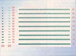
The wettability, or weldability, of solder paste is a difficult property to evaluate because the decision is subjective in many cases. A target trial was developed using a 6-mil laser-cut template for contact print on a 3-inch square area of a multipurpose OSP coated test board (FIG. 1). Twelve plates were printed for each type of solder paste and two plates were welded by air reflux with six different temperature curves.

The sample design comes in three shapes. The width of the line interval produced by the pad varies from 8 to 24 mil. It is assumed that the more tin Bridges occur between pads, the better weldability of the material in combination with the temperature curve. Also, measure the average diameter of the 50-mIL circle. Diffusion of the 50-Mil circle generally follows the result of a pad short circuit, but it is rare to have diffusion of solder on a complete circle. So this part of the experiment is the only part that's subjective.
The small pad to the left of the pad short circuit area is used as an indication of the wetting condition of the solder pad such as SOIC (small outline integrated circuit). Template openings range from full coverage at the bottom of the two columns (85-mil long) to only 23% coverage at the top (20-mil long). The higher the arrangement of these pads is, the better the solderability, because the difficulty of the pads increases as the pad coverage decreases.

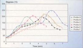
The curves in Figure 2 and Table 1 differ in the mode of preheating (flat insulation vs. diagonal heating), peak temperature, total time, and time for liquefaction. Curve A shows how A formula will interact with superalloys such as 96.5Sn/3.5Ag or 95Sn/5Pb. Curve F simulates a fast 3 to 4 temperature range furnace that is frequently used in the beginning of operation with limited fixed assets. Provide a formula through all 6 temperature curves by summarizing the number of short circuits between line intervals.
The relative "temperature curve sensitivity" can also be calculated by calculating the standard deviation of the melt wetting results for a single curve and then dividing by the average bridging interval for all six curves. Materials with small melting and wetting differences between the curves will be considered insensitive to temperature curves.

Solder bead/tin ball
Although rare, solder balling is generally acceptable in no-wash formulas; But not solder beading. Solder beads are usually large enough to be visible to the naked eye and, due to their size, are more likely to detach from flux residue and cause a short circuit somewhere in the assembly. Solder beads differ from tin balls in several ways:
1. A tin ball (usually larger than 5-mil in diameter) is larger than a tin ball.
2. The tin beads are concentrated on the edges of larger sheet elements very far from the bottom of the plate, such as sheet capacitance and sheet resistance 1, while the tin balls are anywhere within the flux residue.
3. Tin beads are large tin balls that run away from the side of the element rather than forming a solder joint when the paste is pressed under the body of the sheet element and during reflux.
4. The formation of tin spheres is mainly due to the oxidation of tin powder, usually only one or two particles, before or during reflux.
Solder that is not aligned or overprinted may add beads and balls.
Design a test board with a series of sheet element pads, the spacing between the pads varies in size to cover the full range of IPC requirements and beyond. In order to generate tin beads and balls and evaluate solutions for template and pad designs that correct these two common problems, a variety of template opening designs were used, with intentional bias for the opening of sheet elements of 1206, 0805 and 0603 sizes

Figure 3 shows part of the 1206 element on the test board. Similar design logic was used for the test areas of the 0805 and 0603 components. In addition, the test plate is reflow with a different temperature curve as described for the melt test to provide more insight into the optimal reflux curve for a given formula. For each test board, the positions of all beads and balls are recorded, but only the total beads and balls are reported for comparison purposes.
Residue level
Residue levels are another characteristic that is often subjective. Although transparency, color, and visual quantity of flux affect the overall appearance of the final assembly, these factors may not actually be related to the physical quantity of residues that remain on the plate or contaminate the cooler areas and vents of the reflux furnace. For this reason, in addition to subjective issues of visual appearance, residue quantities are determined using thermo-Gravimetric analysis (TGA).
A small sample of the solder paste was slowly heated from room temperature to 50°C above the liquefaction temperature, and weight loss was recorded throughout the temperature rise. This method reveals the actual percentage of solder paste (flux) involved during reflux. The relative amounts of flux components lost during the preheating, reflow, and cooling phases on the reflow soldering temperature curve can also be assessed by a careful review of the TGA's percent-weights-temperature diagram.
other
Test needle testability
Test pin testability refers to the compatibility of flux residues with ICT pin bed test fixtures. Flux must not contaminate standard test needles with sticky residue. Industrial testing for this property is still evolving, but some methods report "click" counts until the test needle is cleaned and/or forced through the flux residue sheet. Although flux formulation plays a significant role in the testability of a test needle for a given formulation, the reflux curve also has a significant impact.
viscous
Viscosity is a property of a given formulation rather than a suitability test, but it helps to further differentiate the formulation from a rheological point of view. There are three main types of viscosity meters in the industry:
A. A viscometer usually uses a "T" sensor to move in a paste at RPM, Revolutions /minute. This method is the most commonly used, but returns limited rheological information.
B, cone and plate, or plate and plate design, using a set of rotating plates, plate spacing fixed, between the tin paste plate temperature control. The plate usually rotates in a rotational speed range and comes back to rest. As with the single point method, rheological maps are established for a given material, however, over a wide range of shear conditions.
C. The helical viscometer uses a helical sensor to measure the resistance of the paste at various shear rates and calculate the rheological index for a given formulation.
Ion Chromatography
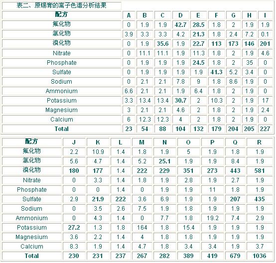
Ion chromatography for flux residue precipitation is a requirement for reliability assessment of disposable paste, but when the same technique is used on raw paste, an understanding of the surfactant can be achieved. Table 2 shows the results of ion chromatographic analysis of primary solder paste for the most commonly used no-wash formulations in the industry. Brominated surfactants are the most popular because they use a limited number of fluorinated and chlorinated compounds. The content is in parts per million.

The results in bold in Table 2 are the result of the original formulation, not the presence of traces of contamination. Adiponate ions (fatty acids) are visible because of the presence of sulfate ions in this experiment. These results show that today's disposable solder pastes, from their original truly "halogen-free" formulas to their final "RMA(Rosin, Mildly Activated) like materials, have large primary solder paste ion concentrations. Probably, since the latter don't pass the test on silver Chromate paper, they should be washed off, even if they are now properly used as no-wash.
Performance compromise
The experiments described here, which have been applied to countless formulations over the years, reveal a number of performance compromises. The main trends are:
<1> Higher printability may result in lower peak holdup.
<2> Higher solids result in lower adhesion.
<3> Finer powder results in higher peak adhesion.
<4> Finer powder results in better close spacing printability.
<5> More diffusion may result in more solder beads.
<6> More diffusion may result in better melting on the OSP.
<7> Lower residue levels on backflow welded plates may result in poor weld wetting.
<8> Lower residue levels on reflow plates may result in better test pin testability.
<9> More plate residues result in less residue in the furnace and lower maintenance costs.
<10> More brominates may result in better fusibility.
<11> Better wetting results in less sensitivity to temperature curves.
There are exceptions to the trend described above. Not every feature is equally important for every application, but if you understand these tradeoffs, you can apply them to the formula that works best.
conclusion
For Oems or contract manufacturers, standard procedures for solder paste contribute to the competitiveness of the final product market. Understanding how a particular solder paste will behave in a particular assembly application and making the most appropriate solder paste choice for each situation is a key factor in achieving high productivity. Standard procedures provide in-depth knowledge and an objective basis for comparison, whether the manufacturer uses the paste supplier's conclusions, conducts internal tests, or both.